1
FreeCAD
1267 readers
1 users here now
Your own 3D parametric modeler.
FreeCAD is an open-source parametric 3D modeler made primarily to design real-life objects of any size. Parametric modeling allows you to easily modify your design by going back into your model history and changing its parameters.
founded 4 years ago
MODERATORS
2
Hello, Solidworks refugee here, with some questions on navigating FreeCAD's feature tree.
Example: I want to make this:

Step 1: Sketch on XY, draw rectangle, pad

Step 2: New sketch, draw rectangle, pad

Accidentally forget Step 3, which would have been to sketch and pad another rectangle
Step 4: New body, sketch on XZ, draw circle (or whatever), pad

Step 5: Cut 1st body minus 2nd body.

Step 6: Explode the resulting compound.

Step 7: Realize that I forgot to do Step 3.
What should I do at this point?

In Solidworks, the standard workflow would be to use the "rollback" tool to suppress the boolean operation, add the missing Step 3, then "roll forward" to reapply the boolean operation.
What is the equivalent "best practice" workflow in FreeCAD?
3
4
5
I'm following this tutorial and following it exactly. I've made the exact same drawing so far, exact same constraints, and getting the exact same results until now.
At 13:22 he uses the Pad tool to extrude a ring, and then confirms it. The result is that he has basically built a flange with a hole down the middle.
When I confirm the extrusion, everything disappears. It still shows up in the model box, but I can't see or interact with anything in the main window, and I don't get any errors or notifications.
I can keep sketching, but everything I've done up until now is basically gone. Is this a bug, or am I doing something wrong?


6
I have been playing with FreeCAD since before 1.0, but I couldn't say when I started. I hated it. I come from Siemens NX, and the workflow made no sense at all. It couldn't do what I considered simple tasks I use all the time for work. I want to make one base sketch that I can make multiple features or bodies from, it was super frustrating not to be able to do that. Arrays didn't make sense. I needed to 3D print a replacement part for something of my daughter's, and didn't have my work computer with me. It took me 2 hours to make this part that would have taken about 10 minutes in NX. Or even SolidWorks (which I am also not a fan of, but used it professionally for several years). I could have driven to my office, picked up my laptop, come home, and designed it faster than FreeCAD 1.0.
I tried 1.1 yesterday after watching some videos on it recently, and most of the major problems I had with it seem to have been addressed. Sketching was better, making features from those sketches was better, things just seemed to make more sense. I made another rather simple part in about half an hour, and I think that time will come down as I get more familiar with it. I wish I had my SpacePilot Pro hooked up for it, it's been a while since I've had to rotate things with my mouse. But I have previously had the 3DConnexion driver working with FreeCAD, so I'll be doing that in the future. Fun fact, you can also do anaglyph 3D with FreeCAD if you want do design with those old-school red/blue glasses.
Anyway, here's what I made. It's a base for a Lundby doll house chair for my mom. Originally, it would have had an Eames style base, with a central metal post and legs coming out like a desk chair. I made a tulip-style base, and inserted a metal pin down the center for stability. It was super easy to design and modify in 1.1, with one main sketch revolved. Then, I created a second sketch for the angled top, extruded that, and did a boolean subtract. Super easy, and actually pretty fun to make. Completely different from my previous FreeCAD experiences. I will be coming back to it again, for sure.


Here's what the original would have looked. She doesn't have the footstool, so I figured I could take some design liberties. The Eames's work is fantastic, so is Eero Saarinen's. Why not mash them up?

7
21
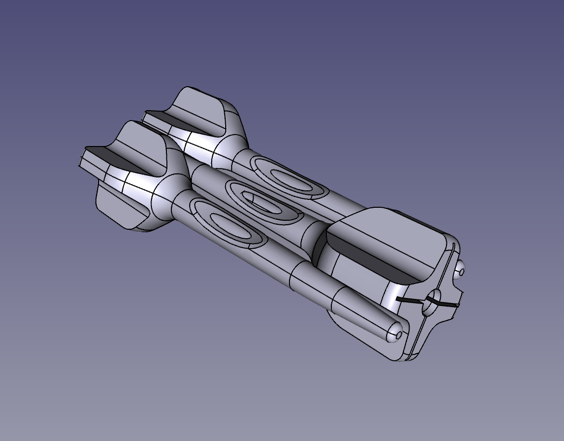
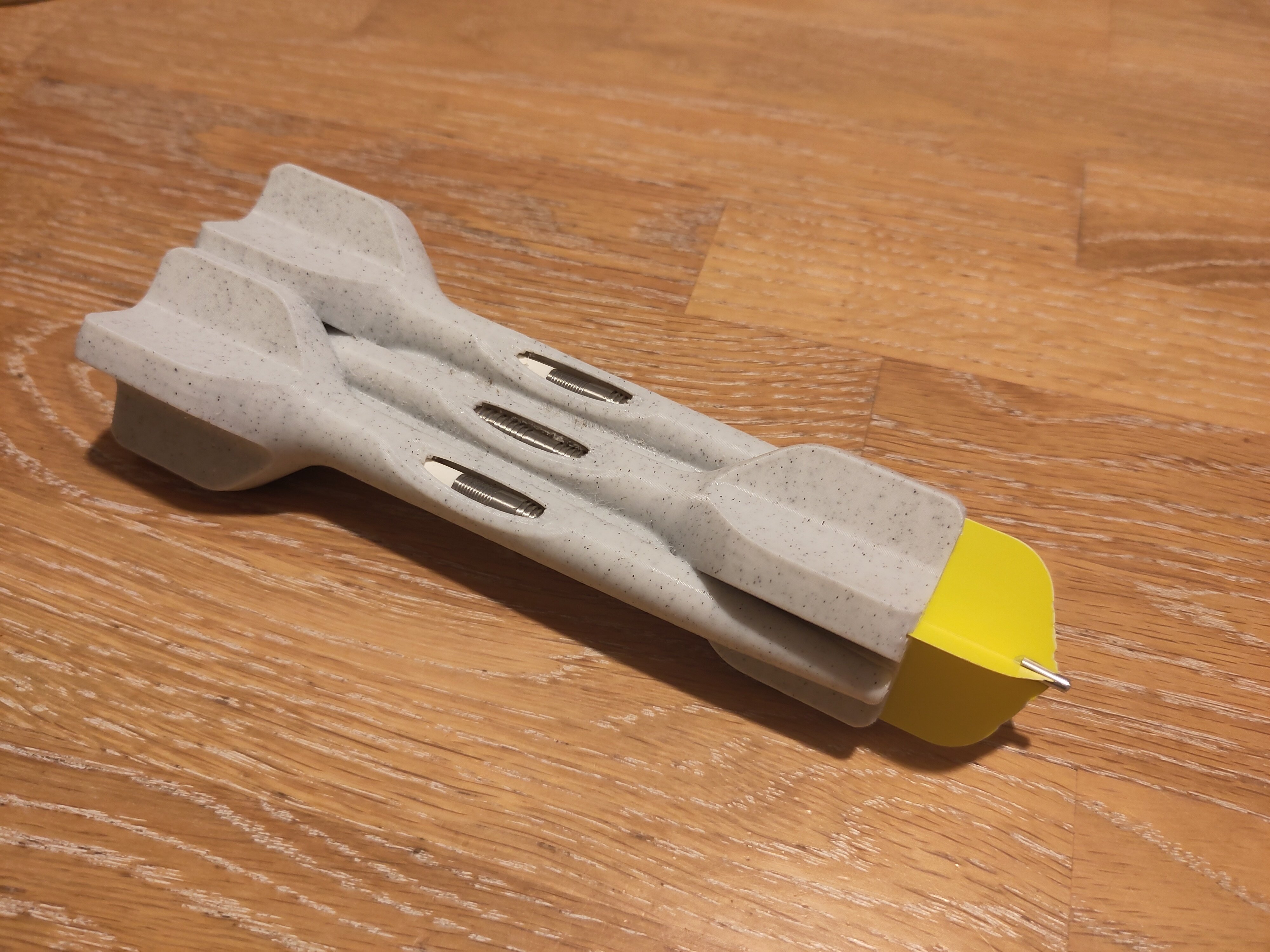
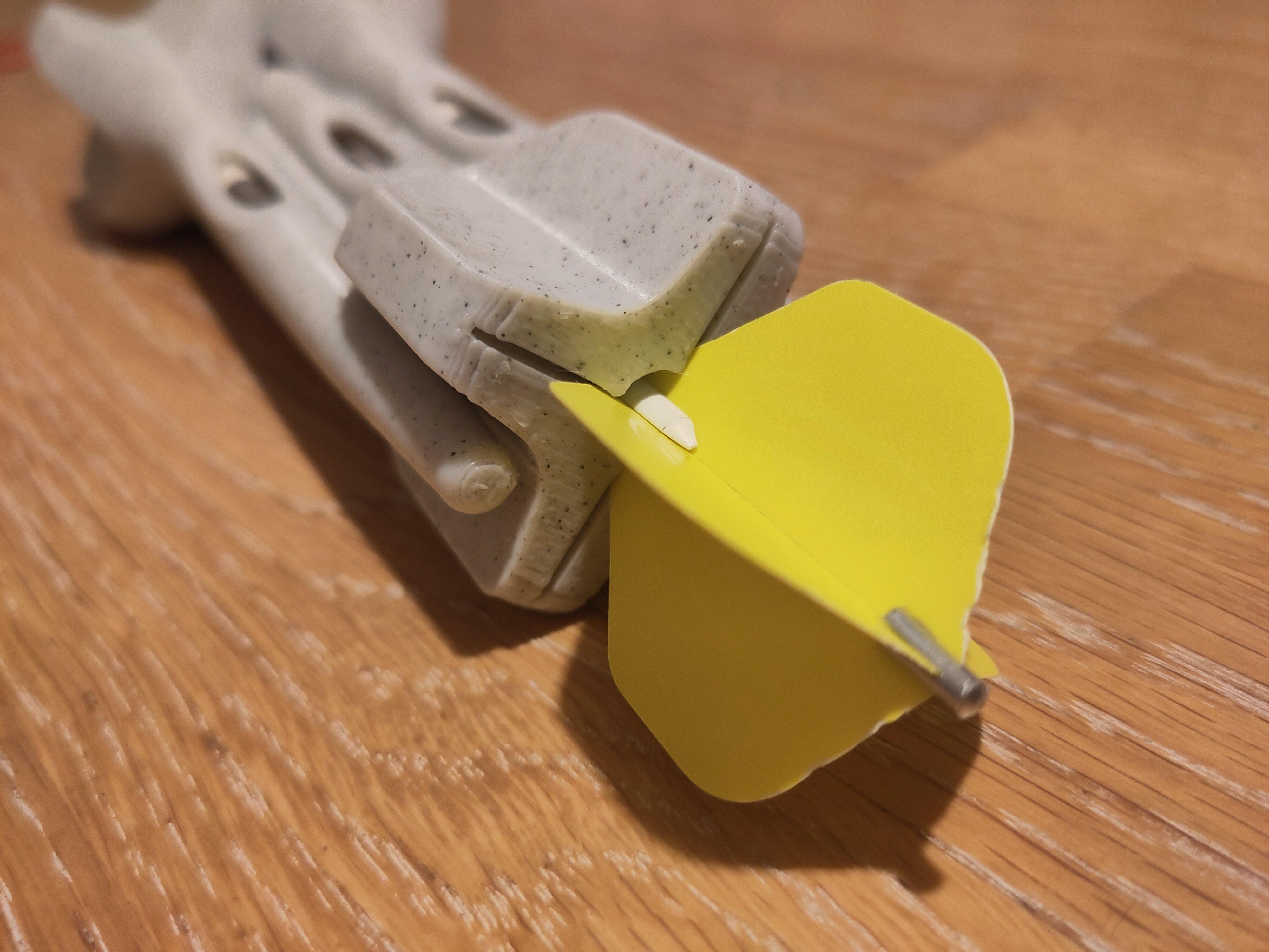
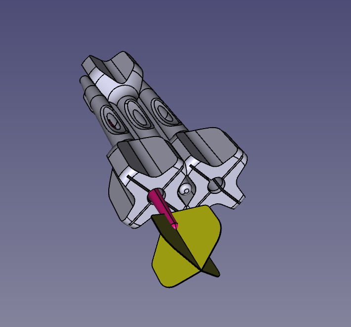
If you wanna print it yourself, the model is here: https://www.printables.com/model/1348194-4n-threaded-flat-head-screws-and-nuts-10-32-equiva
Design to be a drop in replacement for 10-32 screws with a much, much higher pitch. These screws are extremely easy to print, is reliable enough that it can hold some weight.
If you wanna print this yourself, you need to make sure that the screw is sideways, so if it breaks it's no on the layer lines.

Using them in my own prints which had metal screws and they are holding quiet well.
8
9
10
11
12
13

I mean those like that, i did this one manually, but it was quite an annoying process, is there any tool in freecad that can help with these situations?

I have equality between all these lines, but it was still not so pleasant
14
24
Still pretty new to FreeCAD (and CAD in general), any advice on my design before I 3d print it?
(www.printables.com)
15
after bashing my head in my table for a bit, i finally managed to make something "salvagable"... i think.
this is meant to be a vesa adapter, from 200mm to 100mm; the idea is that 6mm metal screw-posts are melted into the holes
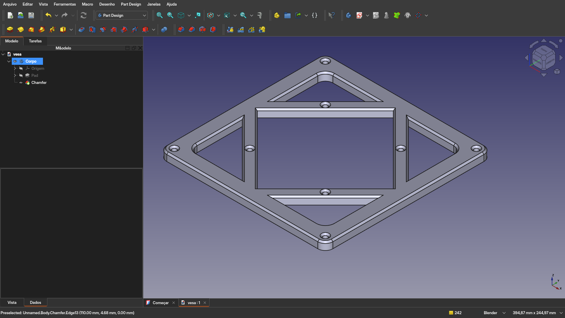
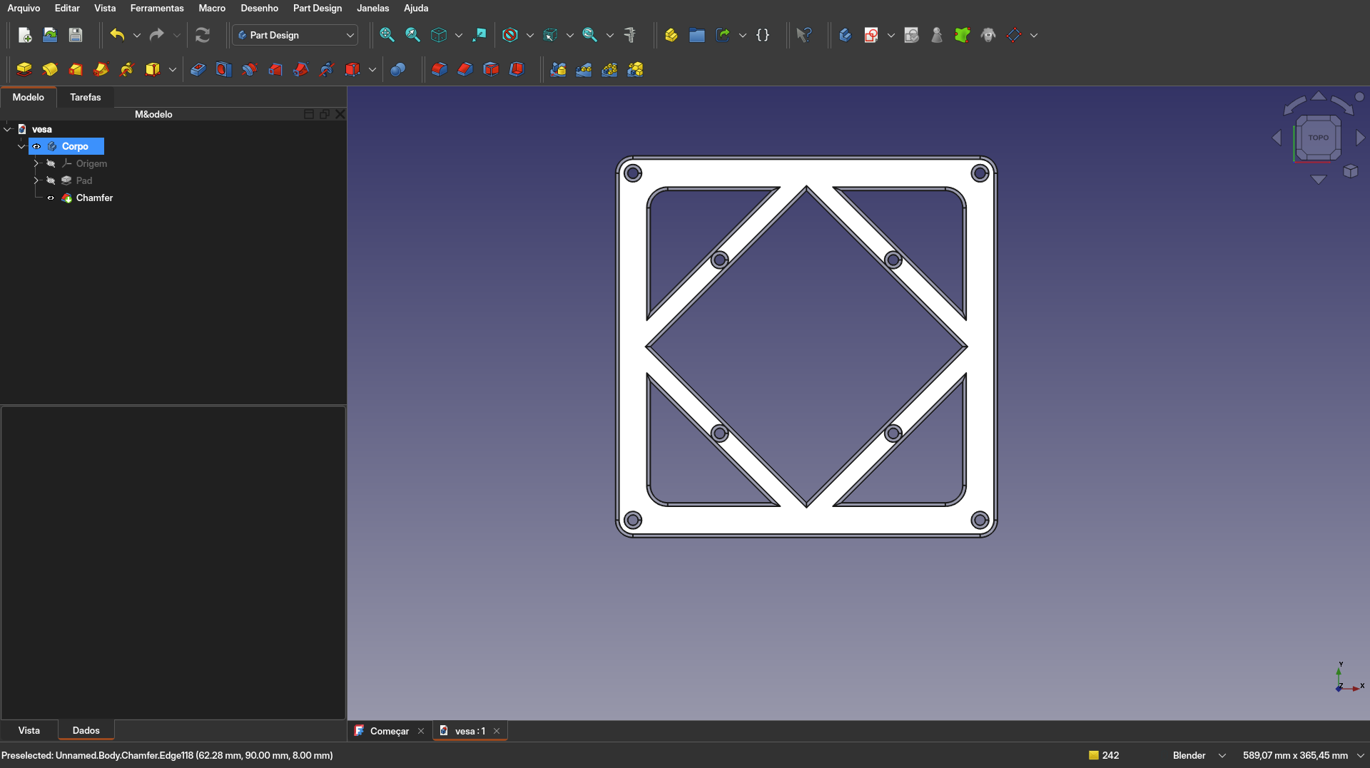
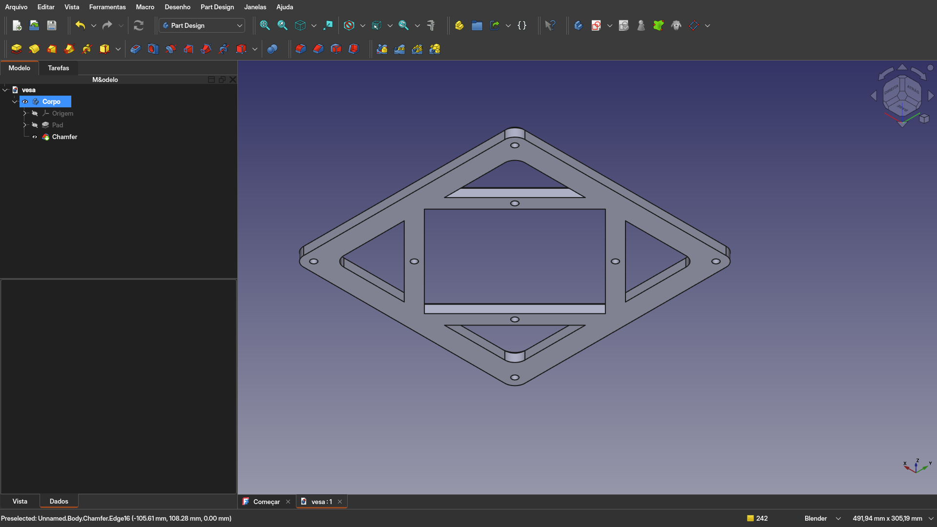
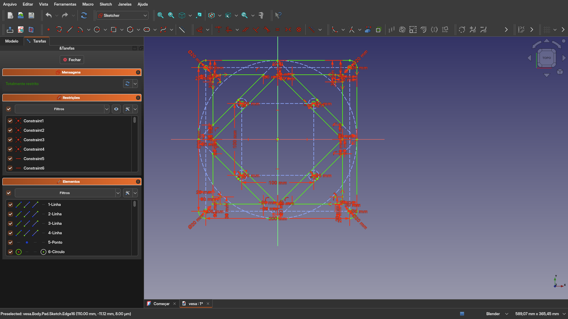
the sketch is quite a bit of a hellscape... i will see if i can figure out symmetry on the next iteration. Do you have any advice on how i can use better this program? it's been quite a bit since i haven't seen such a steep learning curve on a piece of software
17
18
19
20
I love FreeCAD (I use the daily build, 1.1.0dev), but there are two limitations with it that are driving me crazy. Maybe someone can tell me what I'm doing wrong:
-
How can I select hidden features? By that I mean, features that are stacked on top of each other or hidden behind another feature. For example, 2 lines sharing the same space in a sketch, or like in the assembly in the attached image, something inside the box.
In SolidWorks, you can hold Shift (IIRC - I haven't used it in 15 years) and it cycles through the elements that occupy the same space where you click, I can't believe there isn't a similar feature in FreeCAD because it's so essential. But I can't find it for the life of me.
-
In an assembly (new 1.x default assembly workbench), is there a way to manually "grab" parts that aren't fully constrained and move them with the mouse?
Again, in SolidWorks, this is trivially easy to do. I used to use that all the time to quickly see if my parts moved as they should. It's really hard to get a feel for whether the design is correct when nothing readily moves in FreeCAD.
Not to mention, very often, the constraint resolver doesn't quite understand what I want and I'd like to manually locate the parts close to where they ought to be to "help" the resolver, if that makes sense.
Can you do that in the new assembly workbench? That too seems so essential I can't believe it's missing.

21
22
I'm designing a case for a dew-point ventilator controller to be 3d printed. The controller is implemented using arduino on an esp32. The project is based off of the code and HW implementation by Make Magazine Germany: https://github.com/MakeMagazinDE/Taupunktluefter. When starting out I was thinking this would be an easy project but it turned out that especially the lid with its lip and groove design and the parts fixations were not that easy. I'm excited to finally print it.
The file is parametric to some extent and the main footprint is based off of a master sketch. Many parts were imported as step files from grabcad. I used FreeCAD 1.0-rc1 which works like a charm for many things. Next thing I would like to do is to use the new assembly workbench. What do you think?
 Manual "Exploded view",
 Opaque view.

23
24
25
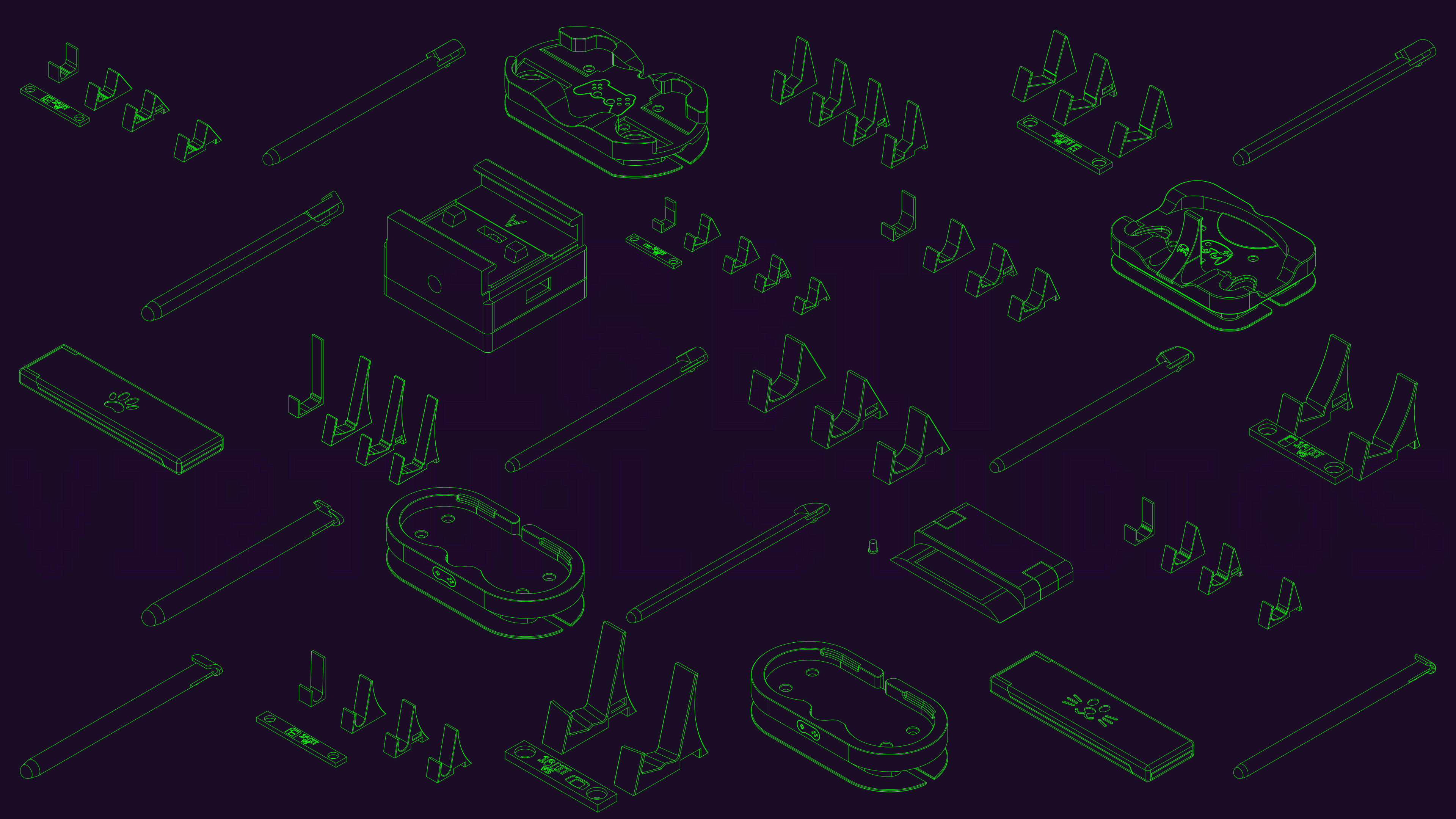
Thank you FreeCAD for not pay walling the ability to create technical drawings.
So what I did to make this was to create a technical drawing of all the designs I wanted and I made this photo in Inkscape.
Was designed to be a banner for my social media, but loved it so much that I'm just using it as my desktop wallpaper.
view more: next ›