I'm back with an update, in case anyone is interested.
If you want to know the lore, here are my previous posts: Do NOT buy Creality, and Creality K1 woes
Quick summary: I still think Creality is garbage.
I started with a used Ender 3 v2 that I picked up cheaply to see if I even liked 3D printing. It drove me insane, but I figured it was old and used, so maybe a newer printer would be better, easier, and less frustrating. During Black Friday 2025, I bought a Creality K1.
It was a nightmare the entire time I owned it.
The machine had constant problems, and Creality did the bare minimum to help. When it became clear that the printer was not reasonably repairable, they still refused to take it back. I ended up reporting the issue to Consumer Protection through Ontario's Ministry of Public and Business Service Delivery and Procurement.
Because of that, the store I bought it from eventually refunded me and took the machine back. I still lost several hundred dollars on extra hotends, replacement parts, repair attempts, and the camera Creality sells separately. I sent all of it back with the K1. During that entire mess, Creality offered me one free replacement part, never apologized, and never made any real effort to make things right.
I'm done with Creality permanently and forever.
That said, I still wanted an enclosed printer. I spent a few weeks researching options, narrowed it down to a few brands, and eliminated them one by one until I landed on Elegoo — specifically the Centauri Carbon 1. I bought it in early April when it went on sale. It ended up costing roughly $100 CAD more than I paid for the K1 during Black Friday.
And honestly? This printer is the absolute tits.
After almost four months and dozens of prints, it has failed twice. Both failures were filament-related, and both were fixed by restarting the print. I've run several brands of PLA and PETG through it, from brand-new rolls to old filament that had been open for months and never bagged or dried. It just chews through everything and puts out clean, reliable prints.
It has been such a relief after dealing with Creality.
The other interesting update is that Elegoo actually followed through on their multi-filament system for the Centauri Carbon. It's called CANVAS, and it's listed at $80 CAD, compared to the $600 Creality wants for theirs. I might buy one eventually, but I'm not an early adopter anymore, so I'll wait until people have the first units in hand.
I've mentioned the Centauri Carbon in comments before, but I wanted to make a proper post after spending enough time with it to feel confident recommending it.
One note: it does not have a dedicated mobile app. That said, I've been using OctoPrint with it, and it has been flawless for me.
TL;DR: I will never buy another Creality product. The Elegoo Centauri Carbon has been amazing and super reliable, and I genuinely think anyone buying a new printer should consider it, at the very least.

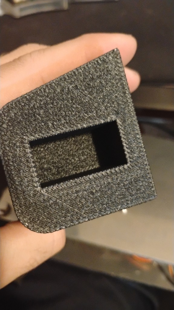
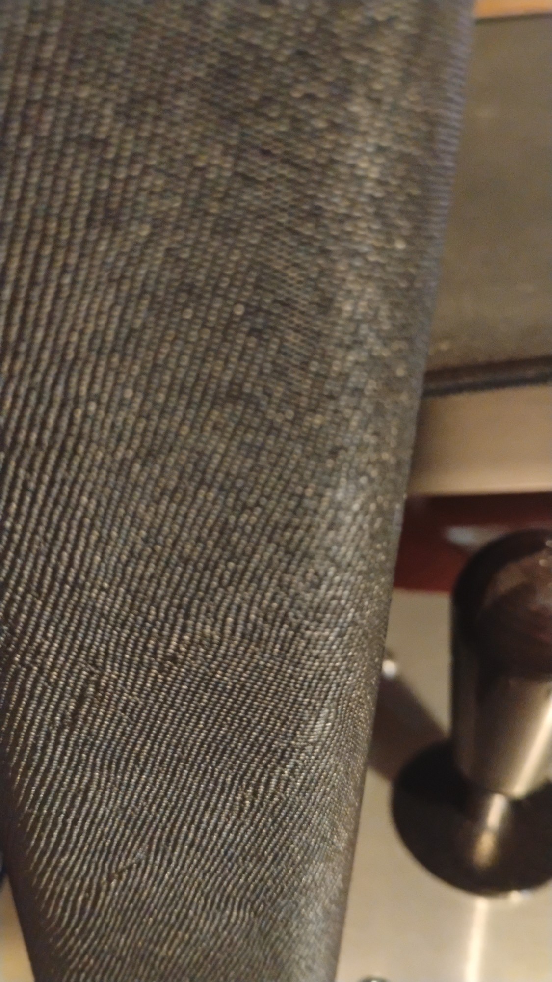
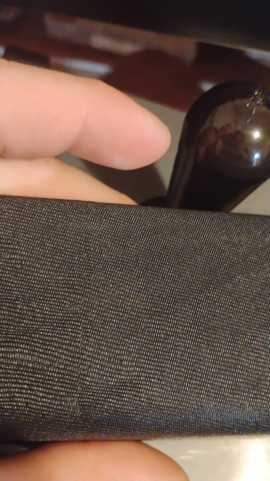


 So after looking at it and pulling it apart and several times missing the window to go look as its happening, it looks like it wasnt extruding enough to actually stick, eventually there is enough of a ball that it sticks and it repeats causing that pattern.


