[-] Rolive@discuss.tchncs.de 3 points 1 day ago

They have no jurisdiction in Europe though.

[-] Rolive@discuss.tchncs.de 4 points 1 day ago

I hope it stays that way.

[-] Rolive@discuss.tchncs.de 6 points 4 days ago

Quitting drinking is easy. I do that several times per day.

[-] Rolive@discuss.tchncs.de 3 points 4 days ago

It was also my first CAD program. Perhaps not having experienced others makes it easier to tolerate the quirks of FreeCAD.

[-] Rolive@discuss.tchncs.de 18 points 5 days ago

I'm quite happy with FreeCAD. It's not really intuitive but I'll gladly take that over any other program with those modern account/subscription/cloud bullshit "features".

[-] Rolive@discuss.tchncs.de 25 points 5 days ago

Upvoted just for Eddie and Richie.

[-] Rolive@discuss.tchncs.de 33 points 5 days ago

Really tiresome to clean I bet.

62
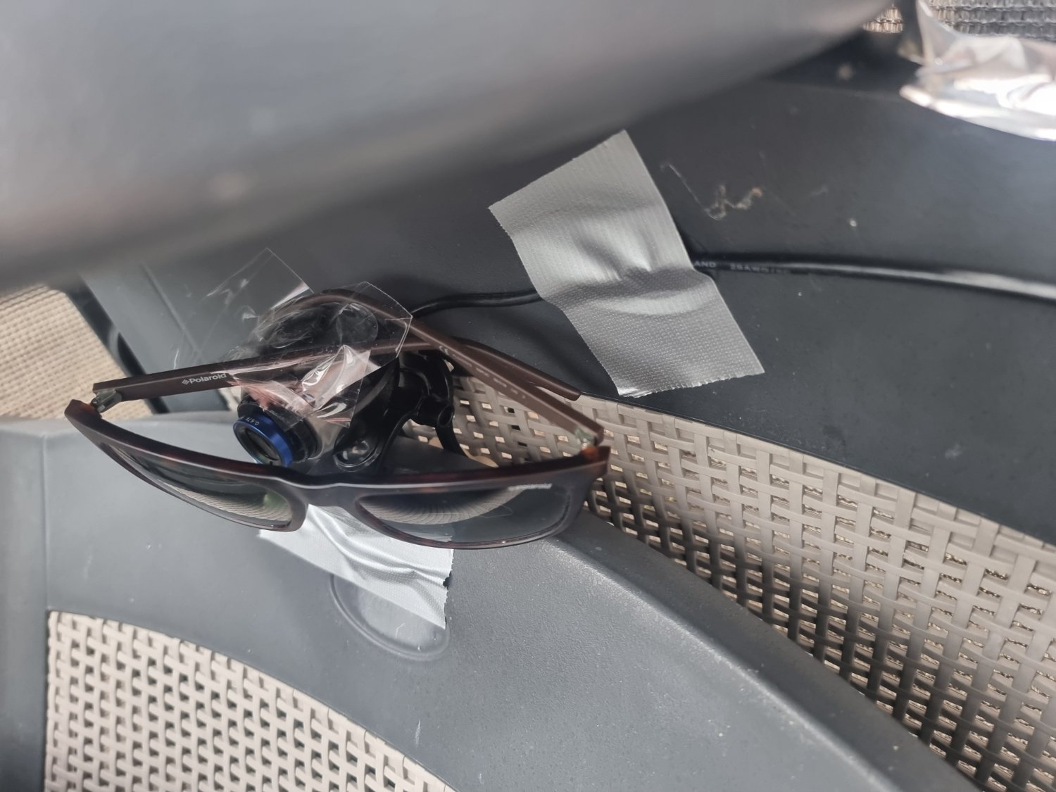
Sun is too bright for webcam (discuss.tchncs.de)
14

According to the A4998 datasheet you're supposed to wait 1 millisecond after waking from sleep to allow the circuit to energise.

What is the worst that can happen if you neglect to do this? I use stepper motors to drive a plant watering pump and losing a step or two really isn't an issue. Is there a risk of damaging the module or is losing the first step the biggest risk?

I trigger the pump by pulling the EN pin low and a 555 timer on the STEP pin makes it pump continuously. It seems sensible to pull the SLP pin down as well with it as that saves a little bit of power.

[-] Rolive@discuss.tchncs.de 202 points 2 weeks ago

It's Afrikaans, not Dutch. It's close though. We can understand written Afrikaans.

19

Hi everyone

I've been experimenting with methods of applying etch resist with a laser and dry film. The process is kind of arduous and error prone.

Developing with sodium carbonate solution to clear unexposed etch resist takes long, doesn't work well and if you leave it too long the developed etch resist will break as well.

I use a laser module attached to a 3D printer to draw the PCB (LCB?) on the etch resist. This laser almost instantly solidifies toner for laserprinters and also almost instantly hardens dry film.

Using powdered toner and a laser would be a much quicker way to apply etch resist since the excess can be wiped off and reused easily. The problem is applying a uniform layer of toner.

Suspending toner on the surface of water and hydrodipping the plate seems to work but drying takes too long.

Spray coating could work but is messy.

Isopropyl alcohol softens the toner too much making it impossible to clean the excess off.

I have not tried using a roller or electrostatic application yet but that could work well.

Does any of you have experience with this and have ideas/advice?

11

LEDs will conduct more current when they get warmer and differences between individual LEDs mean you cannot easily put them in parallel. A constant current DC supply will be good enough for part of the LEDs but will overload some others. To normalize current a series resistor is used with each individual LED.

Now, those resistors waste a bit of power. Are they really necessary? If you put several LEDs in series the individual differences become negligible at some point and a constant current supply will suffice for several strips of series LEDs in parallel.

How many LEDs would this require? Another possibility would be to have the resistor in series with a strip of LEDs.

I got some LED strips off AliExpress that run on 12V and each individual LED has a resistor in series with it. I believe this to be quite wasteful and it would be better to have several LEDs in series with a current regulator instead. The LEDs will end up in an autonomous greenhouse where power efficiency is important.

19

This is an idea that entered my mind. The traditional way is applying some etch resist like toner or dry film, etching away the copper and then adding solder mask before populating the board with components.

Can the solder mask be used as etch resist instead? It feels like skipping an unnecessary step in the process. Why isn´t this more common? This way you won´t need the step of removing etch resist only to replace it with a slightly different compound.

13

It appears to me that UV resin, used for SLA printers should be quite convenient for making PCBs with a laser etcher. You can spread a thin layer of resin on the board and quickly expose it using a laser engraver. It should be most convenient for silkscreen layers that are otherwise difficult to apply.

I think the common method of applying UV mask and spreading it using a piece of plastic sheet is messy and I can never guess how much resin to apply. It's always too much or too little and it's always unevenly spread. And then the UV light exposure is another guessing game.

I have a 500mw 405nm laser module attached to my 3D printer and could easily 'print' some PCB layouts on a thin layer of SLA resin.

Does anyone have experience with this?

7
submitted 6 months ago* (last edited 6 months ago) by Rolive@discuss.tchncs.de to c/askelectronics@discuss.tchncs.de

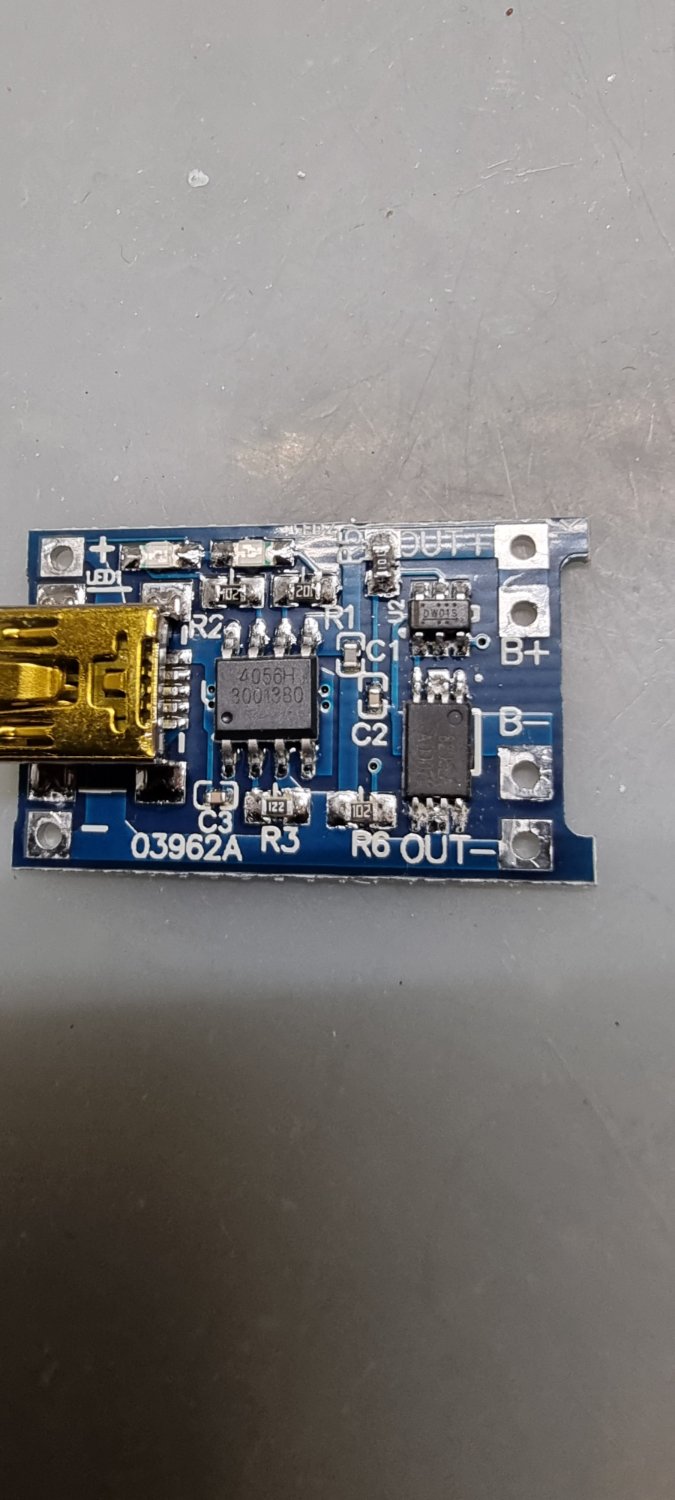
I got these TP4056 modules from an AliExpress vendor and fail to understand how the protection circuit works or if it's just typical Ali shovelware. It could be my limited understanding of electronics.

The protection circuit appears to be just for show. To the right there's a DW01S chip that prevents over charging and discharging in combination with the 8205 dual channel MOSFET.

It looks like the drain of this MOSFET isn't connected anywhere. I've tried following the traces using a multimeter and no other pin shows continuity with the drain. Source1 is connected to Battery - and Source2 is connected to Terminal -.

I suppose the Drain starts participating in the circuit when one mosfet activates.

What was the idea behind this? That the 8205 acts as an AND gate by having them both in series?

I'm trying to make an 18650 testing circuit that uses these modules to charge and discharge a battery and wanted to use the protection circuit mosfet as a trigger for discharging.

9
MOSFET gate resistor (discuss.tchncs.de)

Since MOSFETs have a gate capacitance you'd want to limit the inrush of current from the output of a microcontroller to prevent it from getting damaged prematurely. That's what gate resistors are usually good for.

Another thing is that most MOSFETs don't fully activate with a gate voltage below 10V (n type) so usually a microcontroller pin isn't good enough for switching large loads.

I have a 24V system and have made a voltage divider using two 10k resistors to step down 24V to 12V as gate driving voltage which is pulled down with a weaker MOSFET. The power MOSFET essentially ends up with a 10k gate resistor this way meaning it will take a bit longer to fully saturate.

Is too high harmful? In this situation the load is a heater that activates when the room temperature drops below 18C and deactivates when it gets above 22C so fast switching is not an issue.

25
Artme-3D filament extruder (artme-3d.myshopify.com)

Does anyone here have experience with this? I'm on the verge of buying the Artme3D extruder kit as it seems to be complete with extruder and spooler. Alternatives like FelFil Evo will sell you the spooler for the same price as the extruder which in my opinion is a scam for something that isn't that complicated.

The next challenge is filament degradation. Ideally you add some virgin plastic pellets to recycled plastic chunks so that there is enough plasticizer still left in there. Could you just add the plasticizer yourself? It commonly is glycerol or PEG which are pretty common and easily attainable chemicals. Does anyone here have experience with mixing additives yourself?

33

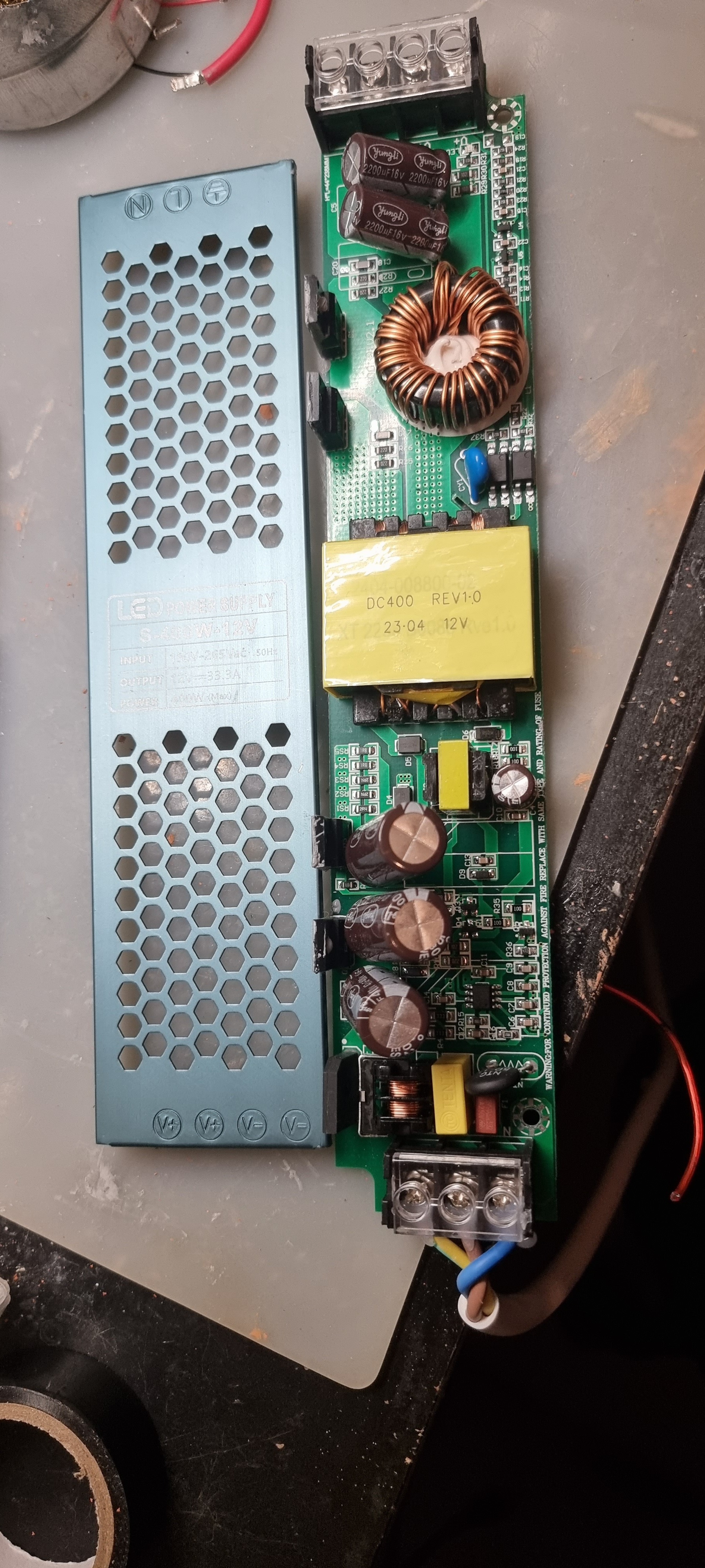
Does anyone recognise these power supplies? They're cheap AliExpress led drivers and I want to change its output voltage to around 22V from 12V. I've read that the way to do this is to adjust the REF voltage on the IC that controls it. It's a KA3845 but I don't understand where that reference voltage is regulated. One voltage is feedback from the output where then other should be a reference.

What would be the best way to approach this? I can't find any schematics on these boards unfortunately.

Thanks.

[-] Rolive@discuss.tchncs.de 57 points 8 months ago

All of them if it wasn't for greedy corporations.

10

Eerste is, ik werk voor een bedrijf zonder CAO al wordt dat hopelijk nog wel ooit iets. Verder ben ik ook geinteresseerd in de rechtsbijstandsverzekering die onderdeel is van sommige vakbonden. Die van CNV kun je bijvoorbeeld ook voor niet-werkgerelateerde zaken inzetten wat wel interessant klinkt. Wat zijn jullie ervaringen?

44

Does any of you have any experience with this? I'm looking at the Felfil Evo pellet extruder which seems like an acceptable option. One thing I don't understand. Why are the shredder and spooler so ungodly expensive?

I mean, can't you just use an old blender to grind pieces down far enough for the pellet extruder? The finer the better no? Airborne microplastic may be a concern at some point.

Also the spooler. Is that more complicated than a stepper motor that runs at a certain RPM spinning the spool around? With perhaps a mechanism that slows down a bit after X rotations to compensate for the spool getting thicker. Nothing an Arduino can't handle. Also don't grip the spool that tightly so pull strength is more or less equal.

Both the spooler and shredder individually cost more than a pellet extruder does..

[-] Rolive@discuss.tchncs.de 198 points 11 months ago

/u/spez is violently taking notes.

view more: next ›

Rolive

joined 1 year ago