89
submitted 5 months ago* (last edited 5 months ago) by Betch@lemmy.world to c/3dprinting@lemmy.world

----SOLVED----

Thank you to everybody for your assistance. I managed to get to where I wanted thanks to instructions provided by @dual_sport_dork

Thank you, thank you, thank you!


Not sure if anyone can help me here. I am pretty lost and confused and wouldn't mind if someone could ELI5 something for me.

I've never used a real CAD software before yesterday night and I'm struggling a bit, I tried googling things but it's just sending me deeper into a rabbit hole of things I do not understand yet.

I'm trying to make this speaker enclosure I've seen just to do something with this shitty bluetooth speaker I have, so I decided to recreate the enclosure myself.

Long story short, I realized I kinda screwed myself after disassembling the bluetooth speaker and now I need to make a 2mm deep pocket on top of the case to snap in the buttons module. I don't really feel like starting the design again from scratch.

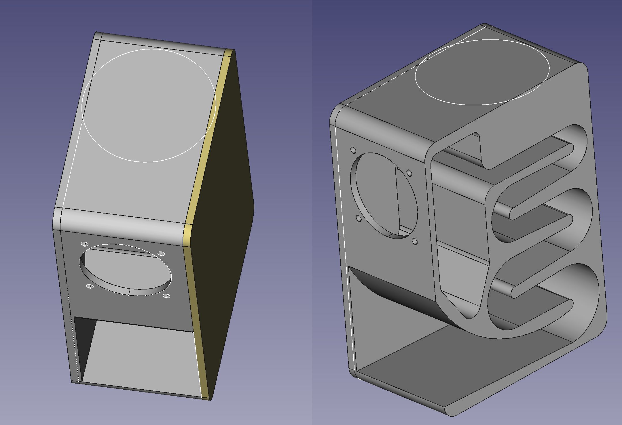
Anyway, as you can see in the attached image, I need to make a big round pocket on top, but both side panels are separate bodies so my pocket only goes through the main body and ignores the 2 other bodies.

I can think of other ways to achieve what I want but I'd really like to figure out a way to do it from where I am right now, if possible. I've seen the term shape binder and "union" in my searches but I can't quite figure it out.

Thank you to anyone who bothered reading this lol

EDIT: For anyone who might see this and is curious about how the enclosure is performing, I finished printing the main body and assembled it to test. Am still missing the side panels and I have to design some kind of flange cover for the driver but here's what I got so far:

Ratchet speaker enclosure test

top 39 comments
sorted by: hot top controversial new old
[-] dual_sport_dork@lemmy.world 34 points 5 months ago

I don't know about the right way to do this, but here's what I'd do:

Go into the Draft workbench. Select the sketch for your pocket circle there, and create a Draft Clone of it, which is the blue sheep icon:

This is not the same as the orange sheep "Partdesign_Clone" command found in the Part Design workbench. Don't ask me why they use the same icon.

If this is the first time you've used the Draft workbench, it will "helpfully" slap a grid on your X/Y axis. If you would like that out of your face, click the "Toggle Grid" button, which may be in your overflow toolbar and has thus fallen off of the right edge of the screen:

Anyhow, this will create a linked clone of your sketch. Anything you do to the original will be reflected on the clone(s) if you have to adjust it later. Create two clones, since you need to apply this to two bodies. Drag one each onto the bodies for your side panels (their root icons are that blue stairstep logo). You can then use these to create a pocket or pad or whatever you're going to do.

If your side panel bodies have their origin set to the same position as your baffle piece in the middle, you won't have to do anything else. Your cloned sketches will be in exactly the same location as the original. If you moved them relative to the document origin, you may have to scoot your cloned sketches around by fiddling with their coordinates in their Attachment properties.

[-] dpkonofa@lemmy.world 12 points 5 months ago

I have no use for these instructions but wanted to say thank you for taking your time to do this. I have been in this type of situation countless times and would kill for a response like this. Thank you for being helpful and useful to someone in need.

[-] zipsglacier@lemmy.world 3 points 5 months ago

Wow, same here. Upvote just for explaining how to turn that dang grid off!!

[-] Betch@lemmy.world 10 points 5 months ago

Ohhhh I really appreciate you taking the time to write this. I'm gonna have to reread this a couple times for my slow brain to get it but I think I might be able to follow and get it to work.

Thank you so much! I'll reply back either once I've figured it out or right before I blow my brains out!

[-] felbane@lemmy.world 6 points 5 months ago* (last edited 5 months ago)

This is not the same as the orange sheep "Partdesign_Clone" command found in the Part Design workbench. Don't ask me why they use the same icon.

They're the same icon because they're both cloning operations — and I'm sure we're all familiar with the story of Dolly the sheep, the first cloned animal.

They're blue and orange because those are the freecad colors for sketch and part respectively.

[-] dual_sport_dork@lemmy.world 6 points 5 months ago

I get that, but from a design perspective it's confusing. Making the only difference between two operations that behave differently only color is also not great from an accessibility standpoint, either.

[-] felbane@lemmy.world 2 points 5 months ago* (last edited 5 months ago)

I don't disagree, was just trying to shed light on the "don't ask me why" part.

[-] Sphks@lemmy.dbzer0.com 4 points 5 months ago

Thank you for your time! You're so kind!

[-] Betch@lemmy.world 2 points 5 months ago

Okay so I've made 2 clones of the sketch from the Draft workbench and put one into each body but it still doesn't seem to apply the pocket to the other bodies.

Not sure if I did something wrong. Create clones of sketch, place them inside each body container for the 2 side panels, switch back to Part Design workbench, select original sketch and then Pocket. Am I doing this right?

[-] lucullus@discuss.tchncs.de 8 points 5 months ago

You only cloned the sketch into the other bodies. You still need to use these sketches in each body to create a pocket. So activate one of the side panels for editing (double clicking on the body in the list, so that the name is bold), then selecting the sketch clone and clicking the pocket symbol in the part design workbench. Set its depth and click ok. Repeat for the other side panel

[-] Betch@lemmy.world 3 points 5 months ago

Yuuup just figured that out now. I just had to use the pocket button and not go into the Tasks tab from the Combo View panel. Thank you!

[-] dual_sport_dork@lemmy.world 6 points 5 months ago

You also have to do a pocket operation to each of the cloned sketches. They will not inherit the pocket from the original sketch -- they only inherit the dimensions of the original sketch itself. In the end you will have three total pocket operations, one each on each body.

Each operation applies only to the body it is attached to in the tree.

[-] Betch@lemmy.world 3 points 5 months ago

Omg that was actually so simple. I thought about that too but I never actually used the pocket button I would always just switch to the Tasks tab in Combo View, but for some reason that tab is empty when you select a cloned sketch so I thought that meant whatever I did to the original would just apply to the clones. The button works just fine though.

Thank you so much for your help!

[-] fluxx@lemmy.world 9 points 5 months ago

Shape binder is what you need. Shape binder can be used to reference geometry from another body. What I would do is I'd make one pocket on the main body. Then select another body and make it an active body. Then select the pocket you made (the surface or the edge) and create a shape binder (part design). This will effectively import the selected feature from the first body and you can reference it from second body. Make sure you hide the first body, as it somehow gets in the way of shape binder, for some reason. Repeat for third body.

[-] Betch@lemmy.world 3 points 5 months ago

Oh, I actually got it working now using @dual_sport_dork's instructions but I will save your comment because that is probably the better way to do things. I'm sure I'll encounter the need for it soon enough hahah. Thank you!

[-] fluxx@lemmy.world 5 points 5 months ago

There is indeed multiple ways of doing anything in freecad. But over time, I prefer staying in Part design as much as possible as this makes it more modifiable and customizable and there are plenty of reasons more for me. But in the end - whatever works is good enough.

[-] Betch@lemmy.world 3 points 5 months ago

Yeah I will keep that in mind for future parts I make. For now though since this is my first time using CAD software I'll stick with good enough hahah

[-] Mac@mander.xyz 7 points 5 months ago

Are you married to FreeCAD? I really like OnShape.

[-] Betch@lemmy.world 8 points 5 months ago

It's an open relationship. I'll have a look! Thanks!

[-] Mac@mander.xyz 4 points 5 months ago

OnShape is intuitive and easy to use. However it does have major downsides (for the free version): all your designs are publicly available and you cannot make money off of your designs without a license or whatever.

Also, due to being web-based you can log on and make stuff from anywhere, which is cool, and they even have an app. Obviously drawing things on a phone is not ideal but it does work—ive done it.

I wish it was FOSS but i always struggled with other applications and OnShape just clicked for me. It was originally recommended to me by a friend and now i recommend it to others.

(Haters please feel free to recommend alternatives—im not married to OnShape).

[-] Betch@lemmy.world 9 points 5 months ago

Oh, yeah no that will be a deal breaker for me hahah. I'd rather stick with FreeCAD in that case as I'm not a fan of web-based for things like that. I want my work to be local and I want to own my designs until I decide to share them.

[-] Mac@mander.xyz 2 points 5 months ago

Yeah, totally understandable. It bothers me a bit.

[-] felbane@lemmy.world 3 points 5 months ago

I dipped my toe into Solvespace for a couple of projects and it's not bad. As with anything it takes some getting used to, and there are things that it does better than freecad (and vice versa).

[-] Mac@mander.xyz 2 points 5 months ago

I will have to check that one out. I haven't heard of it.

[-] bluewing@lemm.ee 2 points 5 months ago

As someone who has tried and used all of the popular commercial and free CAD software - Use what you like and works best for you.

I used OnShape to teach some rudimentary CAD skills to High school students just because it will run on the low powered school issued Chromebooks without problems and it fit the school budget - free. It was easy for me to pickup because I spent years using SolidWorks for a living as a toolmaker.

The most difficult part was getting the kids to use a mouse. Noticeable number are so used to touch pads and screens that they didn't even understand HOW to the the mouse.

[-] stealth_cookies@lemmy.ca 5 points 5 months ago* (last edited 5 months ago)

FYI, I was looking at that exact enclosure for a project I was working on and quickly came to realize that without a bunch of design calculations and redesign for a specific driver it is probably going to be worse sounding than just mounting it into a basic box (with a port if you are feeling fancy).

[-] Betch@lemmy.world 4 points 5 months ago

Oh yeah I don't doubt that for a second. This project is basically just me trying to learn how to use CAD software and I figured this would be a good exercise.

I'm curious to see how bad it'll sound but the enclosure the speaker originally came in was so bad I wouldn't be surprised if it's not any worse, just a different kind of bad.

[-] stealth_cookies@lemmy.ca 2 points 5 months ago

True, if you remodeled it completely the folded horn is a good exercise in sketching in particular!

[-] Betch@lemmy.world 1 points 5 months ago* (last edited 5 months ago)

Yeah I did remodel it completely from scratch. Although I know I didn't do it properly it still taught me a bunch and it will make noise. That part should be done printing in about 2 hours, I'm excited to hear how bad it sounds and to find out how many mistakes I've made in my design hahah.

[-] Betch@lemmy.world 2 points 5 months ago

In case you're curious to hear how mine is shaping out to be, here's a quick demo:

Ratchet speaker enclosure test

I'm actually SO surprised with the results, it completely blows away what it used to be in the original enclosure.

[-] PipedLinkBot@feddit.rocks 0 points 5 months ago

Here is an alternative Piped link(s):

Ratchet speaker enclosure test

Piped is a privacy-respecting open-source alternative frontend to YouTube.

I'm open-source; check me out at GitHub.

[-] HootinNHollerin@lemmy.world 4 points 5 months ago
[-] thegreekgeek@midwest.social 3 points 5 months ago

Looking at the wiki entry for the Part Design toolbox's pocket tool it looks like you can make one through multiple bodies.

[-] Donkter@lemmy.world 2 points 5 months ago

I'm not sure which car you have. I'm still a student so I get AutoCAD as part of my tuition. I believe in AutoCAD you can make cuts in the assembly. Another option might be to save the assembly as one part which I think you can do and edit it from there but then you can't go back to editing each part.

[-] Betch@lemmy.world 1 points 5 months ago

Hmm well I could try something like that as long as I can still export each part as individual STL files. I could just make that my last step. I'll look into that, thank you!

Unfortunately I don't have AutoCAD but I do have friends that have it. As a last resort I can always send them my file and have them do that last step for me.

[-] Donkter@lemmy.world 3 points 5 months ago

Unfortunately if you want to keep the pieces separate, the best bet might be to sketch it in the assembly and measure the relevant parts in the assebly to change the cuts in each piece.

[-] SonicDiarrhea@lemmy.world 2 points 5 months ago

I haven't used FreeCAD before, but if it's anything like inventor or fusion360, you might be able to edit the individual part and either reload that one part into the assembly or start a new assembly. Do you still have the .ipt file or equivalent for that one piece?

[-] Betch@lemmy.world 1 points 5 months ago

Well it's all in the same file. I created separate "bodies/parts" within the same FreeCAD file but now I'm thinking I might try to split off each part and save them as individual files and then try to merge all three files as one part to make the pocket and then somehow try to split them back with the pocket intact.

[-] tagginator@utter.online 0 points 5 months ago

New Lemmy Post: Need some FreeCAD assistance (https://lemmy.world/post/11876809)
Tagging: #3dprinting

(Replying in the OP of this thread (NOT THIS BOT!) will appear as a comment in the lemmy discussion.)

I am a FOSS bot. Check my README: https://github.com/db0/lemmy-tagginator/blob/main/README.md

this post was submitted on 12 Feb 2024
89 points (97.8% liked)

3DPrinting

14837 readers
8 users here now

3DPrinting is a place where makers of all skill levels and walks of life can learn about and discuss 3D printing and development of 3D printed parts and devices.

The r/functionalprint community is now located at: !functionalprint@kbin.social or !functionalprint@fedia.io

There are CAD communities available at: !cad@lemmy.world or !freecad@lemmy.ml

Rules

If you need an easy way to host pictures, https://catbox.moe may be an option. Be ethical about what you post and donate if you are able or use this a lot. It is just an individual hosting content, not a company. The image embedding syntax for Lemmy is ![](URL)

Moderation policy: Light, mostly invisible

founded 1 year ago
MODERATORS